5 Common Machine Guarding Violations & How to Avoid Them
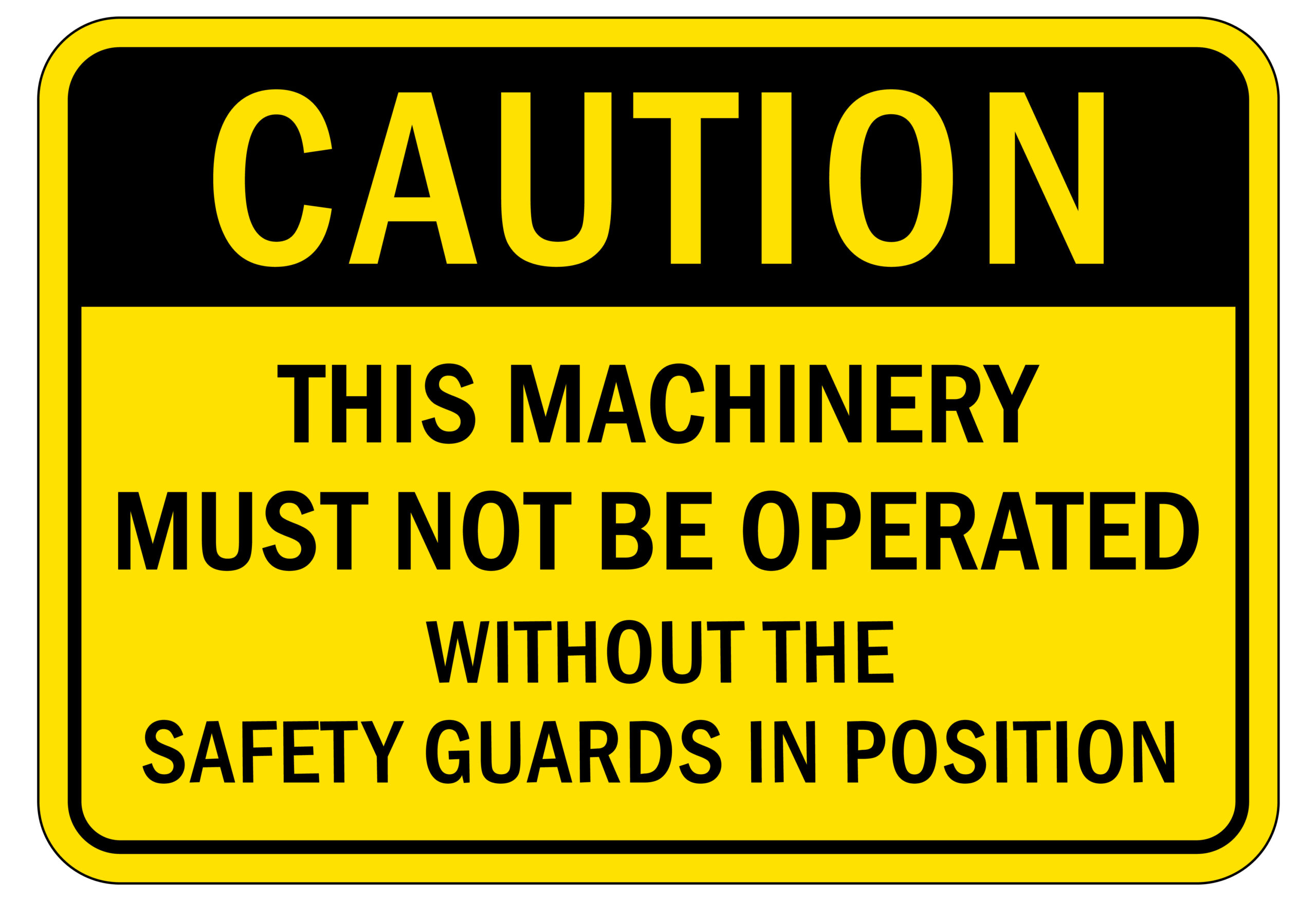
Nearly 18,000 workers are injured every year from guarding violations. This article explores how to avoid the most common machine guarding violations.
Safe, robust, easy-to-use machine guarding requires a careful design. Some engineers still like to start this process with pencil and paper, but most go straight to CAD.
CAD can be split into (relatively) inexpensive 2D systems and costly 3D systems. Both are suitable for designing industrial guards, but their strengths and limitations differ.
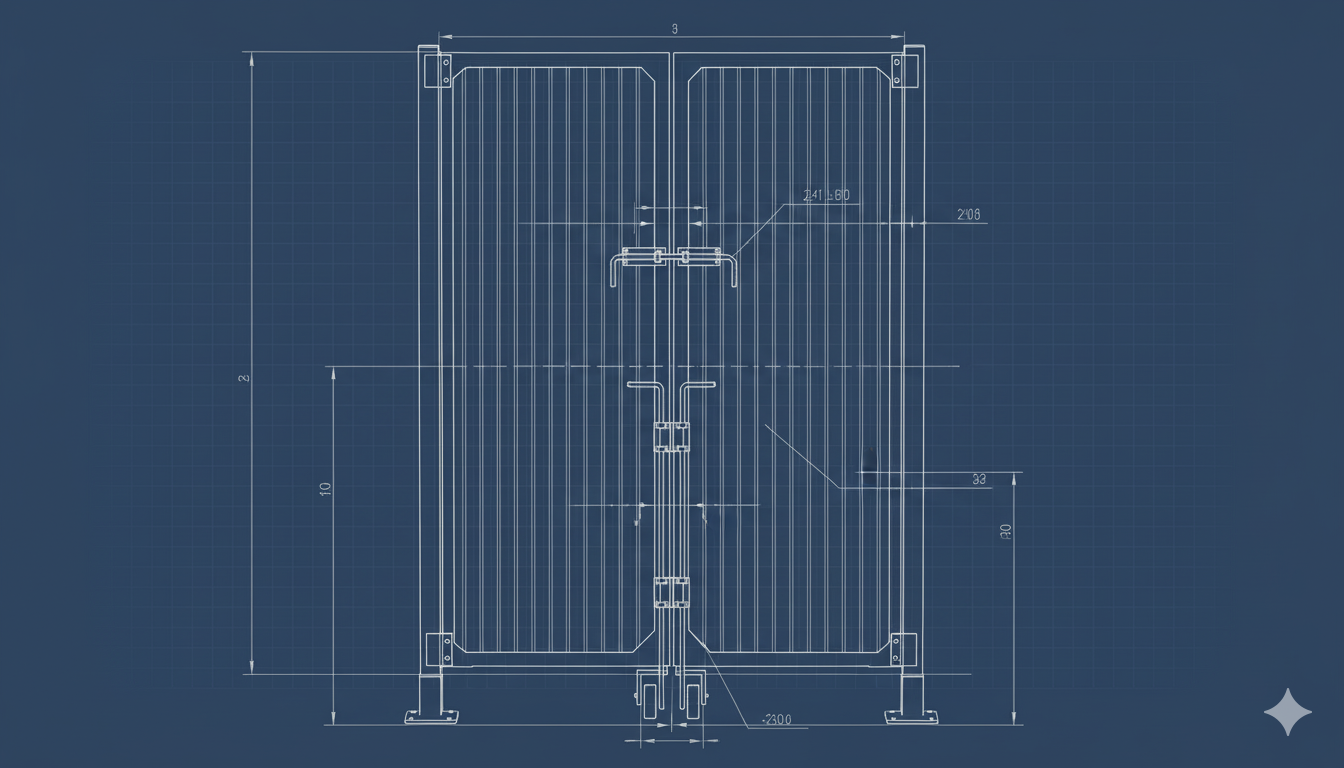
2D design is the older “traditional” style of engineering used to create flat drawings of shapes from three (or more) orientations. These drawings will often have dimensions applied to key features, and they may also incorporate “isometric” views that show how the part will look from a particular angle, so in that sense, they may offer a third dimension.
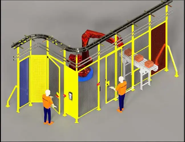
3D design is used to create objects that can be rotated and viewed from different angles. So, a ball wouldn’t just be a circle on a piece of paper, but a representation of an actual sphere that can be rotated to reveal what’s written around the surface.
In CAD, 3D design is often called parametric modeling, which refers to how a change made in one feature creates changes in every related feature. It’s a lot more complex than 2D, so it requires more sophisticated software and a powerful computer to handle the dramatic increase in calculations.
Additionally, most 3D design software can create 2D drawings that can be printed out and used in manufacturing.
Both 2D and 3D are suitable when using CAD design for guarding projects, subject to the limitations listed above. However, you should always consider:
Rather than waste time pursuing (and implementing) ineffective solutions, partner with ROBO FENCE®.
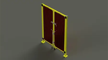
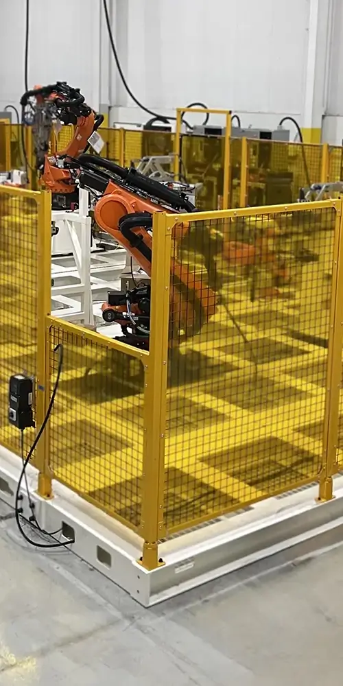
ROBO FENCE® offers all the materials you need to create a safety system, including posts, panels, and gates. All products are manufactured in the United States through our partner, Square Group LLC. We also provide design and consulting services, with 2D and 3D capabilities.
Visit our website to learn more about our products or contact us today to get started with a design consultation. If you want to do your own design work, please browse our library of 3D CAD models.
Contact one of our experts to get started on your next machine guarding project. Until then, browse our complete catalog to see our offerings.
Square Group LLC
Proud Manufacturers and Suppliers of ROBO FENCE®